




















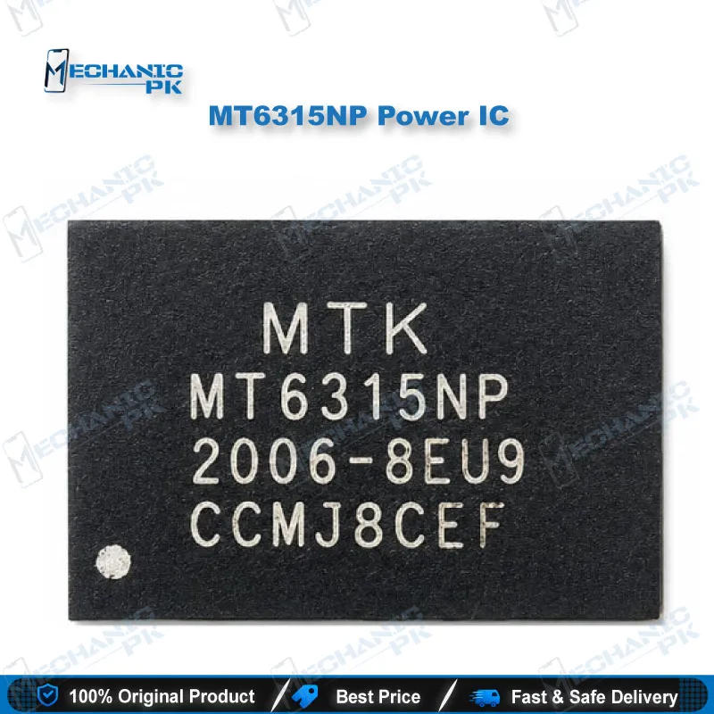
MT6315NP Power IC – MediaTek PMIC for Mobile Repair
₨ 400
MT6315 Power IC for Mobile Repair Diagnostics
The MT6315 is a MediaTek power management IC with four buck regulator outputs, configured over the SPMI bus. Your bench value comes from knowing which rail it feeds, because one chip can supply several subsystems on a board. Its 45-ball WLCSP package is compact, so rework needs a controlled hot air process and steady microscope work. Use this page to check verified electrical limits, the package profile, and the diagnostic steps that help you decide between a PMIC replacement and a faulty load.
MT6315 Power IC for Mobile Repair Benches
The MT6315 power IC for mobile repair work is a MediaTek power management chip that carries four buck regulator outputs. You configure it over the SPMI bus, and efuse settings decide how those outputs can combine. That design means one PMIC can feed several supply rails, so a single fault can make a handset look dead in more than one place. When a phone shows no power on one subsystem, you need to know which rail feeds it before you lift any component. This guide gives you the verified electrical limits, the package details, and the bench steps that shorten diagnosis. Read the sections in order if you plan a replacement, or jump to rail testing if a board is already on your bench. A MediaTek buck regulator IC like this one rewards a measured approach more than guesswork.
Where the MT6315 Fits in the Power Tree
Your power tree starts at the charger or battery input and branches through regulators toward the processor, memory, radio, and peripheral blocks. The MT6315 sits in that tree as a step-down converter with four buck outputs, and each output can feed a different load. Because the outputs can combine under different efuse settings, the rail names on a schematic may not map one to one onto the physical pins you probe. Trust the schematic for intent, then confirm with a voltage measurement at each test point. Start with the input voltage, confirm that the SPMI communication lines show activity, and then measure each buck output in turn. A healthy rail holds a steady voltage inside its expected window, while a rail that sits at zero or drifts points either at the PMIC or at a shorted load downstream. Log each reading as you go, because a pattern across several rails often tells you more than a single measurement.
Key Technical Characteristics
The MT6315 family covers an output voltage window from 0.4V up to 1.19375V, which matters when you compare a replacement candidate against the original rail requirements. The listed maximum input voltage is 6V, so check that your source rail stays below that limit during power-on and charger transients. Operating temperature is specified from -30°C to 85°C, which matches the range you expect from a handset board in daily use. The IC ships in a 45-WLCSP (2.35×3.44) package, a footprint small enough to demand fine-pitch rework and careful pad inspection. Its control interface is SPMI, the serial bus used to program regulator behavior. You can read these figures on distributor listings, but verify them against the official MediaTek datasheet before you commit to a replacement part. Some distributor titles cite a 5A rating, so confirm that figure in the datasheet before you size any load around it.
MT6315 PMIC Replacement and Rail Testing
A replacement job starts with evidence, not assumption. Before you lift the MT6315, confirm the fault sits on the PMIC by checking the input rail, the SPMI lines, and the surrounding passives for shorts to ground. Run a continuity test before any heat goes in, because a shorted capacitor or failed load can mimic a dead regulator and send you to a new IC for no reason. A hot air station with controlled temperature and a microscope for alignment give you the best chance of a clean rework on a 45-ball package. After reballing or replacing the IC, measure each buck output against its expected window, then check ripple on the scope before you power the handset at full load. Inspect pads under magnification for flux residue and bridges, since those faults cause intermittent failures that look like a bad PMIC. Keep a log of readings from each rail so the next technician can repeat your checks and see exactly where the repair changed the board.
| Weight | 0.1 kg |
|---|
Key Features
- Four buck regulator outputs for multi-rail power designs
- SPMI control interface for regulator configuration
- Efuse settings determine how outputs combine
- Output voltage window from 0.4V to 1.19375V
- Maximum listed input voltage of 6V
- Operating temperature from -30°C to 85°C
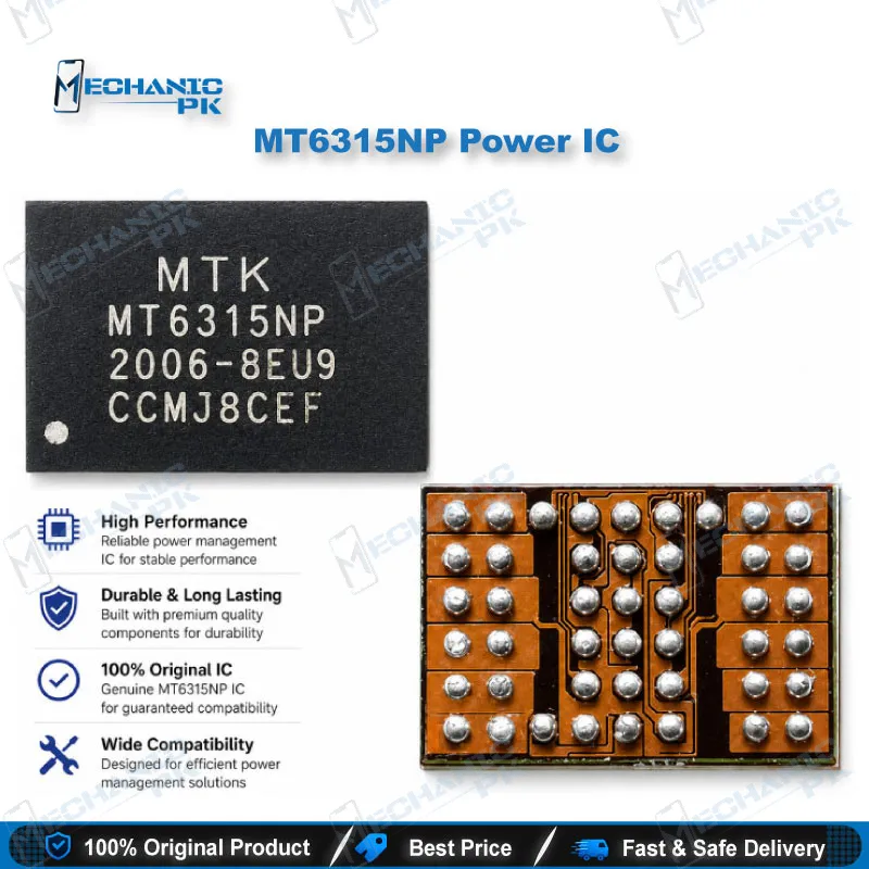
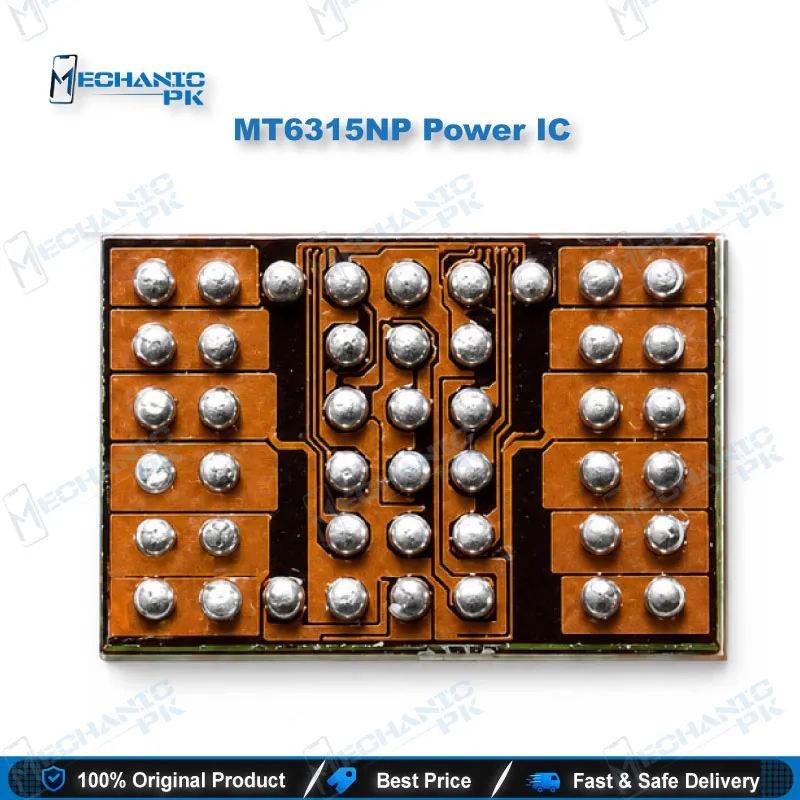
- Compact 45-ball WLCSP package measuring 2.35 x 3.44 mm
- Listed under MediaTek’s GENIO 1200 PMIC range
Specifications
| Brand | MediaTek |
|---|---|
| Category | Power Management IC (PMIC) |
| Technology | Four-channel buck regulator with SPMI control |
| Compatibility | MT6315 PMIC family, SPMI interface |
| Input Voltage | Up to 6V |
| Output Voltage | 0.4V to 1.19375V |
| Dimensions | 2.35 x 3.44 mm (45-ball WLCSP package) |
Common Repair Uses
- Diagnosing dead phones with no power on a single subsystem
- Tracing a missing or unstable buck output with a multimeter
- Replacing a faulty PMIC after rail and SPMI checks confirm the fault
- Verifying ripple on buck outputs with an oscilloscope after rework
- Checking input rail voltage before condemning the PMIC
- Locating shorts between PMIC outputs and downstream loads
- Reballing or reworking the 45-ball package with hot air
- Confirming board stability after a boot loop or charging issue repair
Compatible Devices
- Verified scope is chipset family and interface, not individual phone models.
- Verified listings: MT6315GP/B and MT6315LP/B (MediaTek, 45-WLCSP)
- Platform reference: MediaTek GENIO 1200 PMIC listing
- Control interface: SPMI-controlled power designs only
- Output scope: four-buck power rails (vbuck1 to vbuck4 channel naming)
- Input scope: rails at or below the 6V listed maximum
- Package scope: 45-ball WLCSP footprint only
- Phone model list: not device-specific, so verify against your board schematic
- Replacement scope: match part number and package before ordering
FAQ
What is the product name?
What is the brand of this product?
What is the model of this product?
What is this product used for?
Which devices are compatible with this product?
Who should use this product?
What is the maximum input voltage of the MT6315?
What output voltage range does the MT6315 provide?
Related products