





MT6360PP Power IC – MediaTek PMIC for Mobile Repair
₨ 450
MT6360PP Power IC for Charging and Power Rail Repair
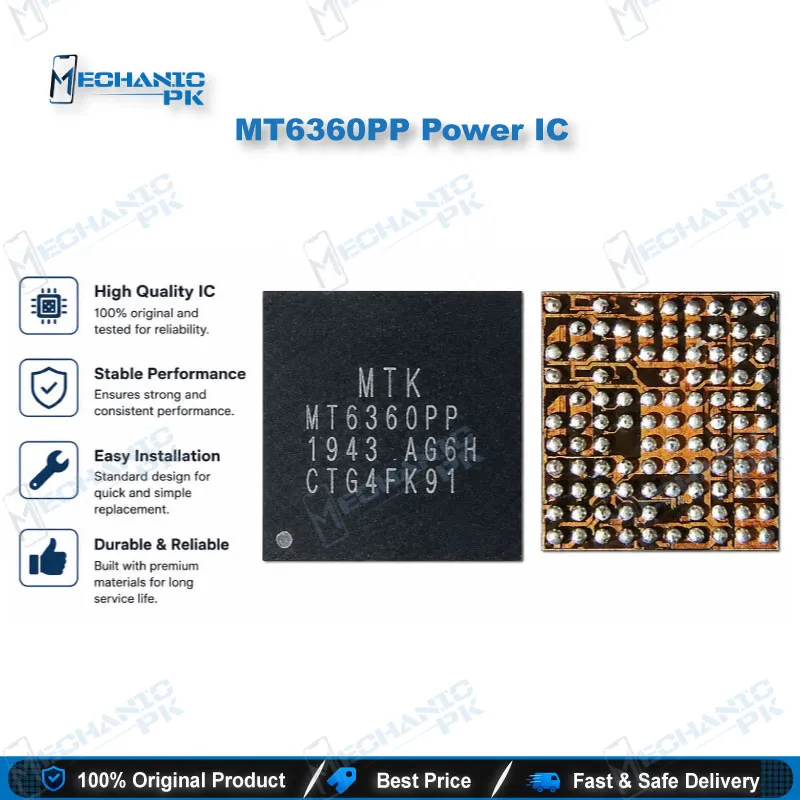
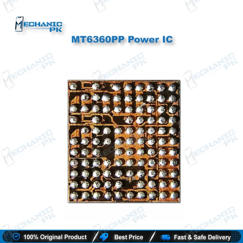
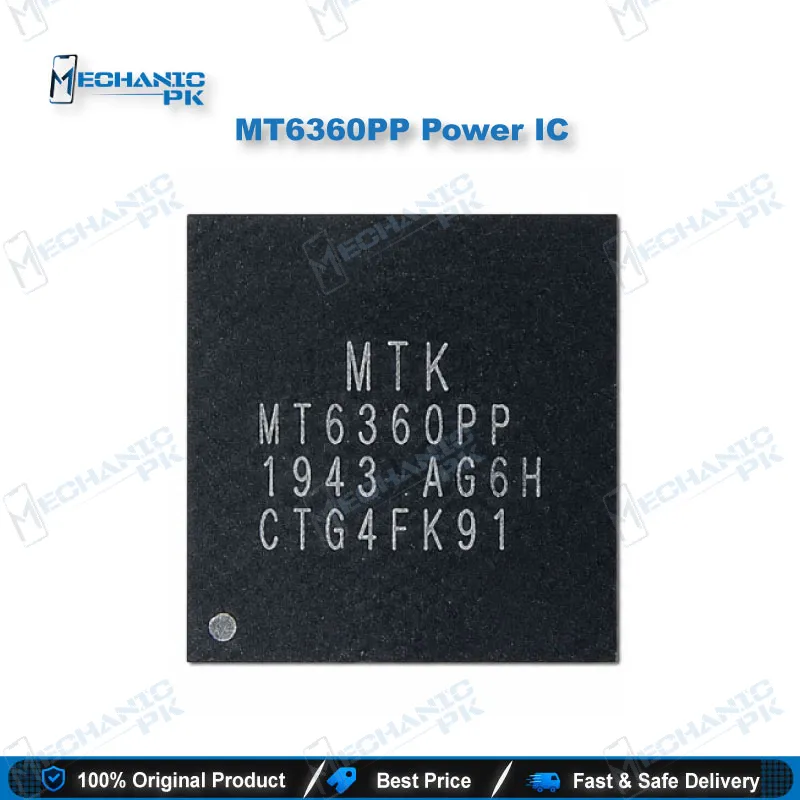
The MT6360PP combines a single-cell Li-ion charger, a USB Type-C PD controller, flash LED drivers, RGB and moonlight drivers, two bucks and six LDOs in one chip. For a technician, it covers the charging path, the USB-C handshake, and several rails that feed camera flash, fingerprint, touch, storage and DRAM. It ships in a 103-position WL-CSP measuring 4.64 x 4.14 mm, so bench work calls for hot air rework and a microscope. Verify the part marking before you order, and check the rail map on your board before you lift the IC.
MT6360PP Power IC: Charging and Power Rail Reference for Mobile Repair
The MT6360PP Power IC sits between the USB-C port, the battery and the phone’s power rails, so many charging and power faults trace back to it. MediaTek positions the MT6360 PMIC family for cellular telephones, tablets and portable instruments. The chip combines a single-cell Li-ion switching charger, a USB Type-C and PD controller, dual flash LED sources, an RGB driver, two bucks and six LDOs in one package. The internal BATFET links VSYS to VBAT, so a battery-side fault can look like a charging fault. Start with the input side, move to the battery path, then measure each output rail before you lift the chip. A reliable check uses a current-limited bench supply, a multimeter and the schematic for your exact model.
Charging Path and USB-C Handshake
The MT6360PP Power IC charger is a synchronous switching regulator running at a fixed 1.5 MHz, with its input on CHG_VIN, which accepts 4 to 14 volts. Average input current regulates from 0.1 to 3.25 A in 50 mA steps, so you can match the limit to your test adapter. Charge current programs from 0.3 to 3 A, and battery regulation voltage covers 3.9 to 4.71 V in 10 mV steps. On the USB side, the PD controller detects cable attach and orientation through CC1 and CC2 and supports USB PD 3.0. When the phone shows a charging issue, read CHG_VIN and CHRDETB first, because a damaged port or weak cable can mimic a dead charger. Condemn the IC only after the input path and cable pass on a known-good supply, and check CHG_QONB behavior when a phone seems dead after long storage.
Flash LED, RGB and Moonlight Outputs
The chip drives two high-side flash LED channels, with torch current from 25 to 400 mA per channel and strobe current up to 2.5 A combined. A flash safety timer runs from 64 to 2,432 ms, so a stuck strobe cannot hold the LED on indefinitely. The RGB driver has three channels that sink up to 24 mA each, and the moonlight driver sinks 5 to 150 mA in 5 mA steps. If the camera flash fails while the rest of the phone works, check the FL_VMID and LED current paths on the board before you blame the driver. Torch mode runs through its own bypass path from FL_VINTORCH, so a torch failure and a strobe failure can point to different faults. Test each LED channel with its LED disconnected, because one shorted LED can look like a failed IC.
Bucks, LDO Rails and Protection
Two buck converters deliver programmable outputs from 0.3 to 1.3 V, with up to 3 A each once the input stays above 3.1 V. Six LDOs feed the fingerprint unit, touch panel, SD card, UFS card and DRAM rails, and LDO5 and LDO7 carry 800 mA and 600 mA. FAULTB flags power-not-good status across these outputs, and register settings over I2C still determine each output’s voltage. The die shuts down above 150 °C and recovers between 95 and 125 °C, while built-in ADCs report charger current, voltage and temperature. When a rail reads dead, measure its output against the schematic before you condemn the IC, because a shorted load can pull a healthy rail low. Power the phone from a current-limited supply during these checks so a shorted rail does not damage the IC further.
| Weight | 0.1 kg |
|---|
Key Features
- Switching charger at 1.5 MHz with 0.3 to 3 A programmable charge current
- USB PD 3.0 dual-role controller with cable recognition and alternate mode support
- Two flash LED channels, torch to 400 mA per channel and strobe up to 2.5 A combined
- Three-channel RGB driver at 24 mA per channel, plus a moonlight driver
- Two buck converters with 0.3 to 1.3 V programmable outputs, up to 3 A each
- Six LDOs for fingerprint, touch, storage and DRAM rails
- Integrated ADCs for charger current, voltage and temperature
- Over-temperature shutdown at 150 °C with an IRQ output for I2C
Specifications
| Brand | MediaTek |
|---|---|
| Model | MT6360PP/A |
| Category | Power Management IC (PMIC) |
| Compatibility | MT6360 PMIC family; device-level compatibility not verified |
| Technology | Single-cell Li-ion/Li-Po switching charger, USB Type-C PD 3.0 controller, flash LED driver, RGB and moonlight LED drivers, 2 bucks, 6 LDOs |
| Input Voltage | CHG_VIN 4 to 14 V; VBAT 2.8 to 5 V |
| Output Voltage | Buck outputs 0.3 to 1.3 V programmable; USB OTG output 4.85 to 5.825 V |
| Power Rating | 6 A continuous battery discharge (9 A peak for 1 s) |
| Operating Temperature | -40 to 85 °C ambient |
| Dimensions | 4.64 × 4.14 mm (WL-CSP-103B) |
Common Repair Uses
- Charging issue: checking the CHG_VIN input path and charger status
- Dead phone: measuring the VBAT and VSYS battery-side paths
- Boot loop or hang on logo: verifying LDO outputs against the schematic
- Camera flash failure: testing the FL_VMID path and flash LED channels
- RGB or notification light failure: testing the RGB_ISINK channels
- USB-C detection failure: checking CC1, CC2 and PD_VBUS
- SD and UFS storage rail faults: checking LDO3 and LDO5 outputs
- Shipping-mode recovery: reviewing CHG_QONB behavior
Compatible Devices
- Verified scope is the chipset family and package, not individual phone models.
- Chipset family: MediaTek MT6360 PMIC series
- Part number: MT6360PP/A, WL-CSP-103B package
- Application scope: smartphones and tablets per the product documentation (device models not verified)
- Battery interface: single-cell Li-ion/Li-Po, VBAT 2.8 to 5 V
- USB interface: USB Type-C with PD controller (CC1, CC2, PD_VBUS)
- Flash LED scope: dual-channel high-side flash LED driver
- Rail scope: two buck outputs (0.3 to 1.3 V) and six LDO outputs
- Device-level compatibility: not verified; match the board marking to MT6360PP/A before fitting
FAQ
What is the product name?
What is the brand of this product?
What is the model of this product?
What is this product used for?
Which devices are compatible with this product?
Who should use this product?
What is the input voltage range of the MT6360PP Power IC?
Does the MT6360PP Power IC support USB Type-C Power Delivery?
Related products