






SGM41511 Charger IC – 3A I2C Single-Cell Charger
₨ 300
SGM41511 Charger IC for Single-Cell Li-Ion Charging Repair
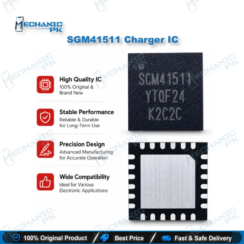
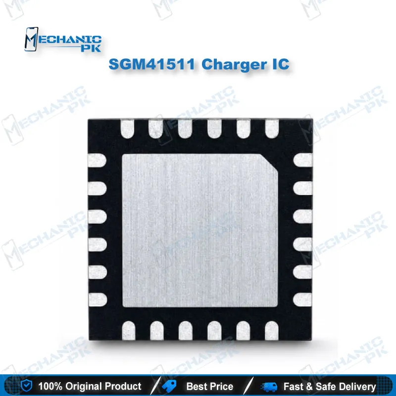
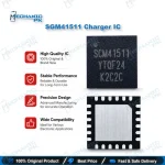
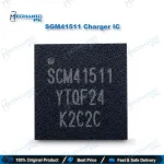
The SGM41511 charger IC is an SGMICRO I2C-controlled 3A single-cell battery charger with NVDC power path management. It integrates the reverse blocking FET, both switching FETs, and the battery FET in a TQFN-4×4-24L package. The synchronous buck stage runs at 1.5MHz and reaches 93% efficiency at 1A from a 5V input. The operating input range spans 3.9V to 13.5V, and the pin sustains up to 20V. A USB OTG boost mode delivers 5.15V on VBUS. If your repair bench handles a charging issue board that carries this marking, you get a datasheet-verified charger IC with full protection features: input over-voltage, thermal regulation, and JEITA-based battery temperature monitoring.
SGM41511 Charger IC: 3A NVDC Charging Stage for Mobile Repair
The SGM41511 charger IC is an I2C-controlled 3A single-cell battery charger from SGMICRO with Narrow Voltage DC (NVDC) power path management. It integrates the input reverse blocking FET, the high-side and low-side switching FETs, and the battery FET in one TQFN-4×4-24L package. When a board reaches your bench with a failed charging stage, you replace one chip instead of rebuilding a discrete circuit. This page lists the verified electrical limits, features, and repair scope so you can match the part against the marking on your board before you order.
Charging Architecture and Power Path Behavior
The SGM41511 runs a 1.5MHz synchronous buck charger through three charging phases: pre-conditioning, constant current, and constant voltage. It starts and terminates a charging cycle without software control, and it begins a new cycle when the battery voltage falls below the recharge threshold. The NVDC power path holds the system voltage slightly above the battery voltage and above a programmable minimum system voltage, which defaults to 3.5V. That design keeps system power alive even when the battery is fully depleted or removed, so you can test a dead phone on a bench supply without a battery attached. When the system load exceeds the input limit, supplement mode draws the shortfall from the battery and protects the adapter from overload. The 28mΩ battery FET keeps discharge losses low, and the buck stage reaches 93% efficiency at 1A and 91% at 2A from a 5V input.
Input Range, OTG Boost, and Protection Features
The operating input voltage range runs from 3.9V to 13.5V, and the device sustains up to 20V at the input. You get programmable input current limit (IINDPM) and programmable input voltage limit (VINDPM), with VINDPM tracking the battery voltage for maximum power tracking. The IC meets USB 2.0 and USB 3.0 power specifications and supports standard USB hosts, charging ports, and USB-compliant high-voltage adaptors. In boost mode, it supplies 5.15V on VBUS with a 1.2A or 0.5A current limit, which covers USB OTG output. Protection covers input over-voltage, input UVLO, thermal regulation and thermal shutdown, charging safety timers, and NTC-based battery temperature monitoring following the JEITA profile in both charge and boost modes. Ship mode leakage sits at 10μA, and the nQON pin handles wake-up and full system reset. The charge voltage regulation accuracy is ±0.5%.
Where the SGM41511 Fits in Your Repair Workflow
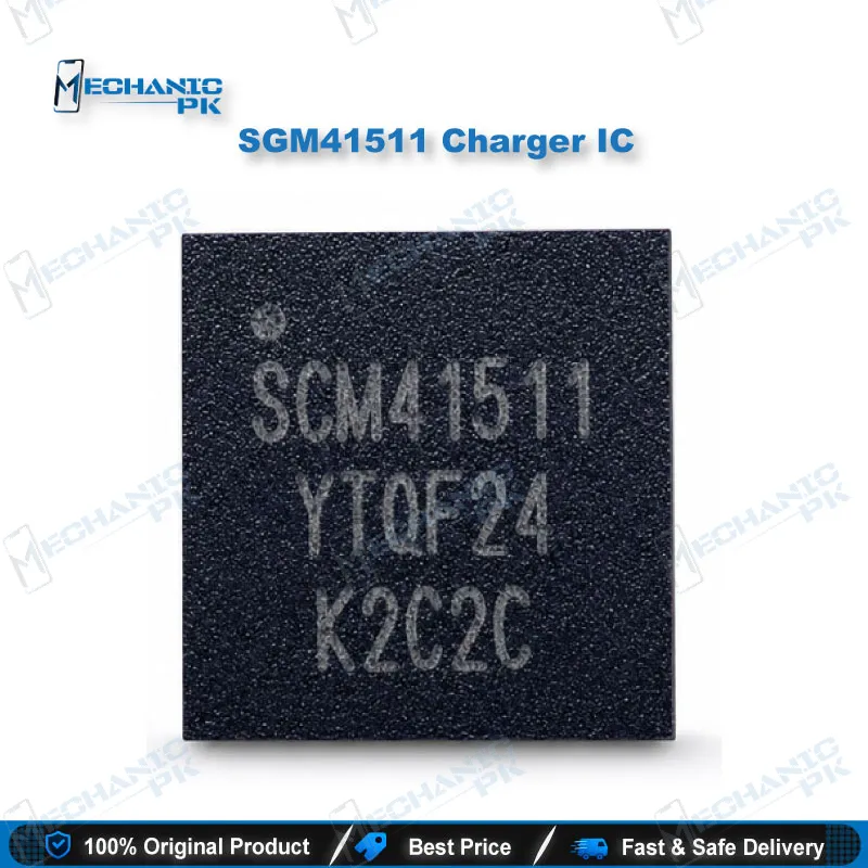
This part belongs to your PCB repair and IC replacement stage, after you isolate a charging issue through diagnostics. Confirm that the chip marking on your board matches the SGM41511 before you plan IC change karna, because SGMICRO sells related charger variants with similar names. Check the board with a multimeter first, then inspect the area under a microscope for lifted pads, burnt traces, or liquid damage residue. A hot air station handles the removal and refit, and a reballing kit helps if your job needs pad restoration on the TQFN footprint. After replacement, test charge start, charge termination, and OTG output on the bench before you return the device. If your shop grows into higher-volume IC rework, the next step up is a precision hot air station with stable airflow control. Browse the Charging ICs category for related charger and power ICs that share this workflow, and pair them with your soldering and rework tools from the same catalog.
| Weight | 0.1 kg |
|---|
Key Features
- I2C-controlled 3A single-cell battery charger with NVDC power path management
- 3.9V to 13.5V operating input range, up to 20V sustainable voltage
- 1.5MHz synchronous buck charger with 93% efficiency at 1A from 5V input
- USB OTG boost mode with 5.15V output and 1.2A or 0.5A current limit
- Fully integrated MOSFETs, current sense, and compensation
- Instant-on operation with a depleted or removed battery
- ±0.5% charge voltage regulation accuracy
- Input over-voltage, UVLO, thermal regulation, and JEITA-based battery temperature protection
Specifications
| Brand | SGMICRO (SG Micro Corp) |
|---|---|
| Model | SGM41511 (ordering part SGM41511YTQF24G/TR) |
| Category | Charger IC |
| Compatibility | Single-cell Li-Ion and Li-polymer charging circuits |
| Supported Devices | Universal — not device-specific |
| Technology | I2C-controlled NVDC power path charger, 1.5MHz synchronous buck, 3A charge current, USB OTG boost mode |
| Input Voltage | 3.9V to 13.5V operating, up to 20V sustainable |
| Output Voltage | 5.15V on VBUS in boost (OTG) mode, up to 1.2A |
| Package | TQFN-4×4-24L, 24 pins |
| Operating Temperature | -40°C to +85°C |
Common Repair Uses
- Charger IC replacement and charging stage recovery on boards that carry the SGM41511 marking.
- IC change karna on boards marked SGM41511 with a confirmed charging issue
- Restoring charging after input surge or over-voltage damage to the charger stage
- Recovering a dead phone that draws no charging current after the charger IC tests faulty
- Rebuilding the charging stage after a USB connector or port repair
- Testing the 5.15V USB OTG boost output after replacement
- Verifying the battery temperature sensing (TS/NTC) circuit after replacement
- Bench validation of charge termination and recharge behavior after repair
- Replacing the charger IC after liquid damage cleanup when the charging stage tests faulty
Compatible Devices
- Universal — not device-specific. Verified scope covers single-cell Li-Ion and Li-polymer battery systems with USB input.
- Single-cell Li-Ion battery systems
- Single-cell Li-polymer battery systems
- Smart phone charging circuits
- Tablet charging circuits
- Portable internet devices and accessories
- EPOS devices
- Standard USB hosts and charging ports
- USB 2.0 and USB 3.0 compliant input sources, including USB-compliant high-voltage adaptors
FAQ
What is the product name?
What is the brand of this product?
What is the model of this product?
What is this product used for?
Which devices are compatible with this product?
Who should use this product?
What input voltage range and OTG output does the SGM41511 charger IC support?
Which package does the SGM41511 charger IC use?
Related products