








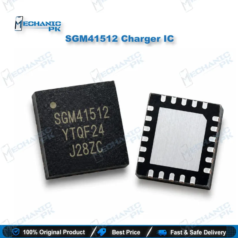
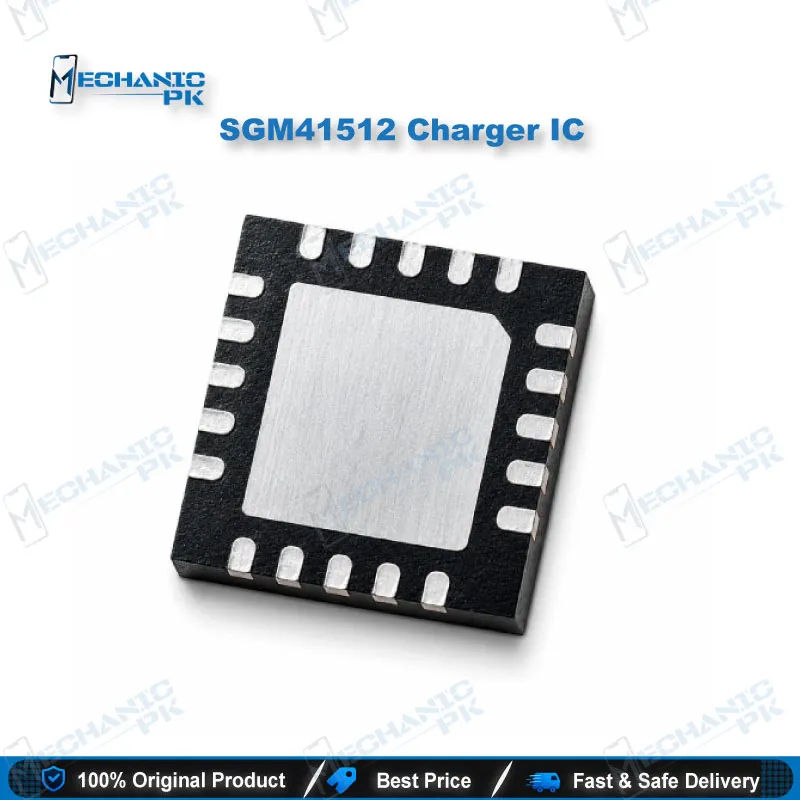
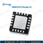
SGM41512 Charger IC 3A Single-Cell NVDC TQFN-24 SGMICRO
₨ 250
SGM41512 Charger IC for Single-Cell Phone Charging Circuits
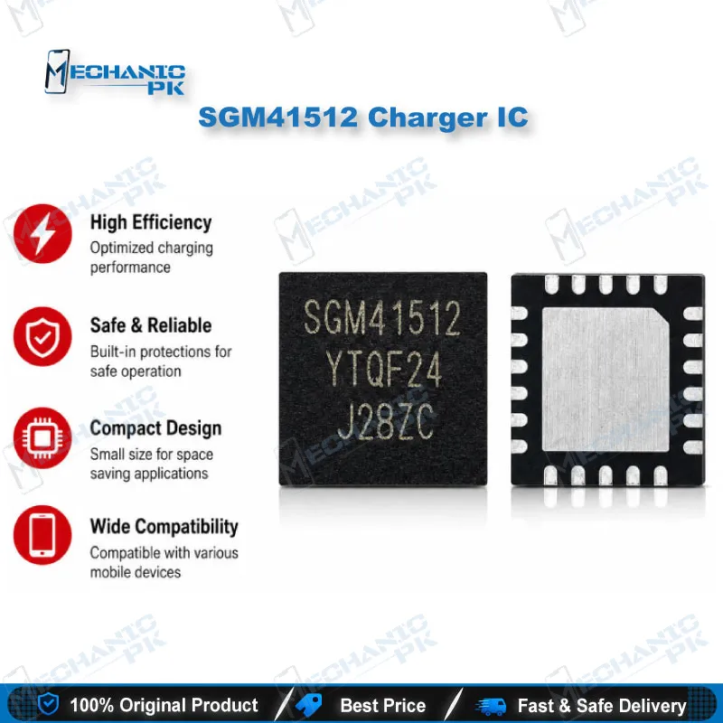
The SGM41512 charger IC from SGMICRO combines a 3A synchronous buck charger with NVDC power path management in one TQFN-4×4-24L package. It runs from a 3.9V to 13.5V input, tolerates up to 20V on the input pin, and charges single-cell Li-Ion and Li-polymer batteries under I2C control from the phone’s processor. Four integrated MOSFETs, built-in current sensing, and USB OTG boost output up to 1.2A keep the external parts count low. Technicians fit this IC when a smartphone or tablet shows a charging issue traced to the charger stage, such as no charging, slow charging, or no OTG output.
SGM41512 Charger IC: 3A NVDC Charging and Power Path Control
The SGM41512 charger IC is SGMICRO’s I2C-controlled switch-mode charger for devices that run on a single Li-Ion or Li-polymer cell. It manages two jobs at once: charging the battery and feeding the system rail through a narrow voltage DC (NVDC) power path. The chip integrates all four power switches: the input reverse blocking FET, the high-side and low-side switching FETs, and the battery FET. It also includes the bootstrap diode, current sense, and loop compensation. A 1.5MHz synchronous buck stage delivers up to 3A of charge current. SGMICRO rates it at 93% charge efficiency at 1A and 91% at 2A from a 5V input. When this stage fails on a phone board, you get the familiar symptoms on your bench: no charging icon, a charger that never gets detected, or a dead phone that will not start from the adapter.
How the SGM41512 Handles Power Path and Charge Cycles
The NVDC power path holds the system voltage slightly above the battery voltage. It never lets that voltage fall below a programmable minimum, which defaults to 3.5V. Because of this, the device powers on instantly even with a deeply drained or missing battery. Dynamic power management cuts charge current when the input hits its current or voltage limit. If the system load keeps rising, the battery supplements the input through ideal-diode operation, so the adapter never overloads. Each charge cycle runs through pre-conditioning, constant current, and constant voltage phases. The IC terminates charging on its own once current drops below the preset level, then restarts when the battery falls under the recharge threshold. Input detection recognizes USB BC1.2 SDP, CDP, and DCP ports as well as non-standard adapters. In OTG mode, the boost converter lifts the battery voltage to 5.15V on VBUS with a 1.2A or 0.5A current limit. Charge voltage regulation holds ±0.5% accuracy, which protects cell health over hundreds of cycles.
Diagnosing a Faulty SGM41512 Charging IC on the Board
The SGM41512 charging IC sits between the charging port’s VBUS line and the battery and system rails. That makes it the first suspect when a phone shows a charging issue with a known-good battery and cable. Start with your multimeter in diode mode on the VBUS line. A short to ground there often traces back to a failed charger IC. Next, connect a USB tester and watch the current draw. Zero or very low current with a healthy adapter points toward the charger stage. Check the TS line and the battery NTC as well. The IC monitors battery temperature through the TS pin under the JEITA profile, so an open or damaged thermistor path can block charging even when the IC itself works. The nQON pin controls ship mode exit and full system reset. A device stuck in ship mode can look dead until you trigger that reset. Rule out these faults before you commit to an IC change karna job, because a replacement chip will not fix a broken sense line.
Fitting the SGM41512 into Your Repair Workflow
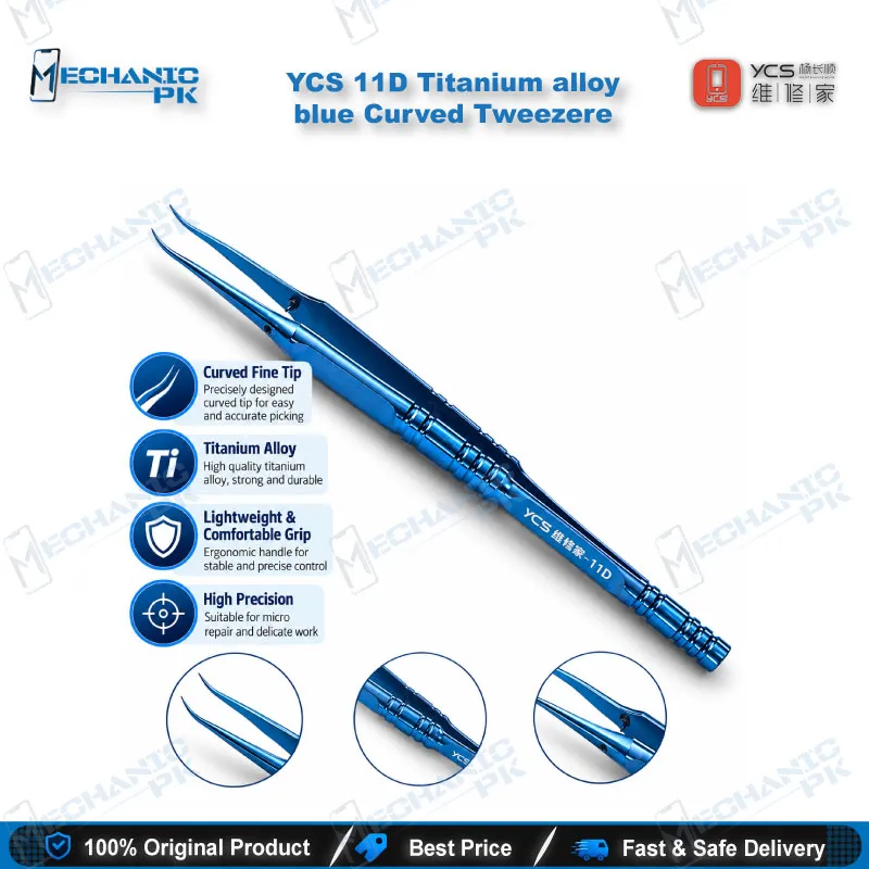
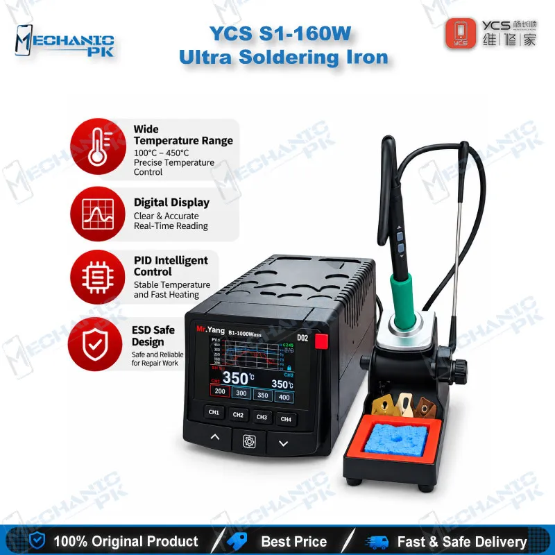
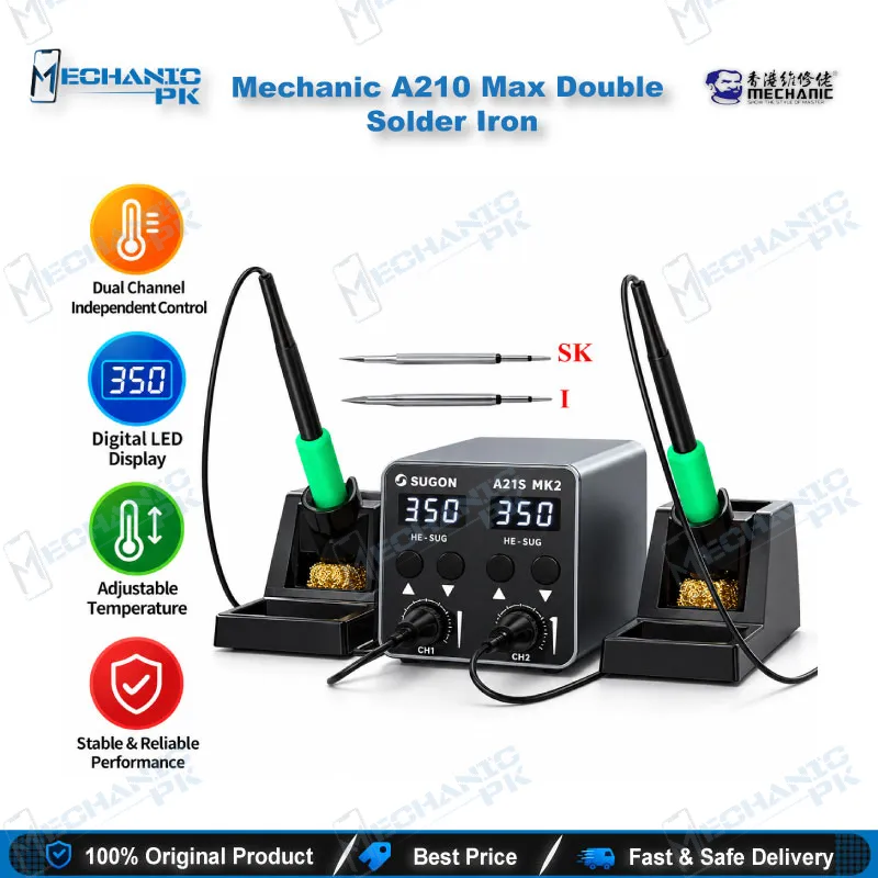
A clean TQFN replacement starts with a PCB holder that keeps the board flat and a hot air station with steady airflow to lift the old chip without disturbing nearby passives. Use a soldering station with a fine tip and quality flux to level the pads and the large thermal pad underneath. A stereo microscope lets you confirm pad alignment and catch solder bridges on the 24 fine-pitch terminals before power-up. After fitting the new IC, run the board on a DC power supply and verify charge current with a USB tester. Confirm the full part marking against the board before ordering. SGMICRO publishes the SGM41511 under the same 3A NVDC family description, so check the board’s original marking rather than swapping by family name. For technicians who handle QFN charger work daily, a trinocular microscope with a camera is the natural upgrade for documenting each job.
| Weight | 0.1 kg |
|---|
Key Features
- 3A single-cell charging with a 1.5MHz synchronous buck converter
- 3.9V to 13.5V operating input with 20V sustainable input tolerance
- NVDC power path for instant-on with a depleted or missing battery
- USB OTG boost to 5.15V with up to 1.2A output and hiccup over-current protection
- Auto detection of USB BC1.2 SDP, CDP, DCP, and non-standard adapters
- ±0.5% charge voltage accuracy and 28mΩ battery discharge switch
- JEITA battery temperature sensing, thermal regulation, input OVP, and UVLO
- Ship mode with 10μA battery leakage and full system reset via nQON
Specifications
| Brand | SGMICRO |
|---|---|
| Model | SGM41512 (ordering part SGM41512YTQF24G/TR) |
| Category | Charging IC / Battery Management IC |
| Compatibility | Single-cell Li-Ion and Li-polymer batteries |
| Supported Devices | Smartphones, tablets, portable internet devices, EPOS terminals |
| Technology | I2C-controlled 1.5MHz synchronous buck charger, NVDC power path, USB OTG boost |
| Input Voltage | 3.9V to 13.5V operating, up to 20V sustainable |
| Output Voltage | 5.15V on VBUS in OTG boost mode |
| Power Rating | Up to 3A charge current; up to 1.2A OTG output |
| Dimensions | TQFN-4×4-24L package (4mm × 4mm, 24 pins) |
Common Repair Uses
- Phone not charging with a known-good battery and adapter
- Slow charging traced to the charger stage
- Charger not detected or no charging icon
- Dead phone that will not start from the charger
- VBUS line short to ground caused by a failed charger IC
- OTG port not powering USB accessories
- Abnormal heating around the charging section during charge
- Charger IC change after liquid damage near the charging circuit
Compatible Devices
- Verified at the battery-chemistry and board-design level. SGMICRO publishes no phone model list, so match the part marking on your board.
- Smartphones that use the SGM41512 as their main charger IC
- Tablets with a single-cell battery and an SGM41512 charging stage
- Single-cell Li-Ion battery systems
- Single-cell Li-polymer battery systems
- Devices charging from USB SDP, CDP, and DCP ports (BC1.2)
- USB OTG-enabled devices using the 5.15V boost output
- Portable internet devices and accessories
- EPOS terminals
FAQ
What is the product name?
What is the brand of this product?
What is the model of this product?
What is this product used for?
Which devices are compatible with this product?
Who should use this product?
Can I replace the SGM41512 with an SGM41511 on a phone board?
Why does a phone still not charge after changing the SGM41512?
Related products