




















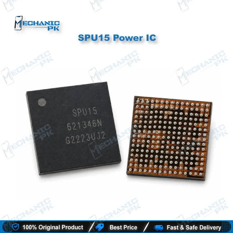
SPU15 Power IC – PMIC for Mobile Phone Repair
₨ 900
SPU15 Power Management IC
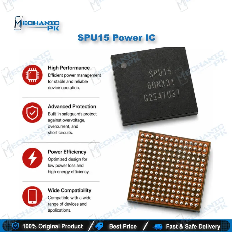
The SPU15 is a power management IC (PMIC) built for mobile phone motherboards. It sits in the power stage and manages voltage distribution across the board, so a fault here typically shows as no power, dead phone behaviour, or boot instability. Supplied as a surface-mount component for board-level rework, it suits technicians working with hot air stations and standard reflow tools. Confirm fitment against the donor board or schematic before installation. Stock a reliable PMIC source for power-stage repairs in your workshop.
SPU15 Power IC: Role in the Mobile Power Stage
The SPU15 power IC is a power management integrated circuit (PMIC) for mobile phone motherboards. Its job is to control how voltage is regulated and distributed across the board after the battery and charging stage. When a PMIC in this role fails, technicians commonly see dead phone symptoms, no power response, or boot loop behaviour, although these symptoms overlap with other faults. For a technician, the SPU15 is a board-level component that calls for careful diagnosis and controlled soldering. This guide explains where the part sits in the power workflow, how to confirm the fault before replacing it, and what to watch during rework.
Where the SPU15 Fits in the Power Stage
Power management ICs take input from the battery and charging path, then supply regulated rails to the processor, memory, and peripheral circuits. The SPU15 belongs to this group, so its role is distribution and regulation rather than data processing. That distinction matters on the bench. A failed power stage component can affect several rails at once, which is why the symptom alone rarely identifies the faulty part. Treat the SPU15 as one link in the chain and map it against the schematic of your target device before ordering stock.
Compatibility is the step that most often goes wrong. Pin layout and rail assignment can change between board revisions, so a part that looks identical may not match your device. Confirm the exact model and board revision, then cross-check the PMIC marking against the donor board. Where fitment is not confirmed, verify before ordering rather than relying on a broad model list. This habit saves rework time and protects your repair record.
Fault Diagnosis Before Replacement
Start with a bench power supply and check current draw on the board. An abnormal idle current points toward a shorted rail or a failed regulator, while a normal draw with no startup suggests a different stage. Check the charging IC, battery connector, and main CPU short points before you desolder anything. Comparing voltages on the PMIC output rails against the service manual confirms whether the part is doing its job. A PMIC that passes these checks is not the fault, so avoid replacing it blindly.
Diagnosis also depends on sequence. Test the battery connector and charging path first, since a shorted charging stage can mimic PMIC failure. Record the readings so you can compare them after the swap. If the voltages stay wrong after replacement, look for secondary damage on the same rail before assuming the new part is faulty. Careful measurement at this stage keeps you from replacing working parts.
Rework and Reflow Notes
Clean the pads with flux and remove residue before placing the new part. Use a hot air station at controlled temperature, and shield neighbouring components to avoid heat damage. Inspect the solder joints under a microscope for bridging once the component cools. Pair the job with a reliable reballing kit and PCB holder for stable handling. After reflow, recheck the power rails before closing the board.
Handling matters as much as the soldering itself. Store fine-pitch ICs in a dry, ESD-safe container and avoid touching the pins with bare hands. Preheat the board evenly so the part does not warp the pads during reflow. A steady process, rather than rushed heat, gives the most consistent results across a busy workshop. Clean joints and stable voltages are the two checks that confirm the repair holds.
| Weight | 0.1 kg |
|---|
Key Features
- Surface-mount package for board-level hot air reflow
- Power management function for voltage regulation across the board
- Suited to power-stage fault repair workflows
- Compact footprint for fine-pitch rework
- Works with standard reballing, microscope, and PCB holder tools
Specifications
| Model | SPU15 |
|---|---|
| Category | Mobile Phone Power Management IC (PMIC) |
| Technology | Power Management IC (PMIC) voltage regulation |
| Package | Surface-mount (SMD) |
Common Repair Uses
- Dead phone and no-power diagnosis
- Boot loop investigation at the power stage
- Abnormal idle current diagnosis
- Power rail restoration after board-level rework
Compatible Devices
- Mobile phone motherboards (power stage repair)
- Confirm model and board revision before ordering
- Verify rail assignment against the donor board
FAQ
What is the product name?
What is the model of this product?
What is this product used for?
Which devices are compatible with this product?
Who should use this product?
Does a faulty SPU15 cause dead phone or boot loop symptoms?
Does a replacement SPU15 need software steps afterward?
Related products