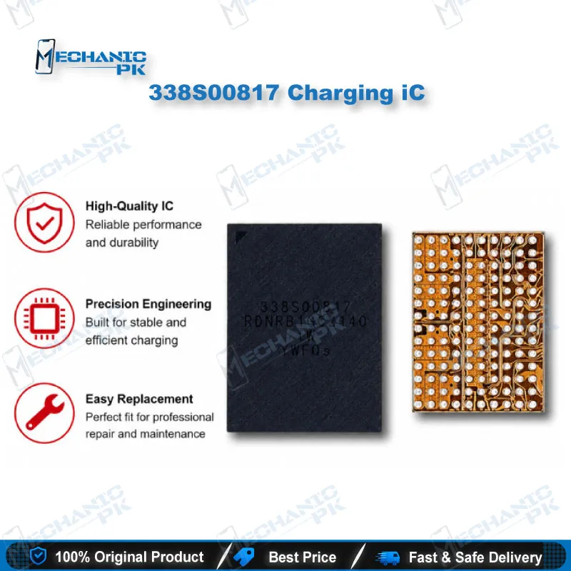
















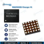
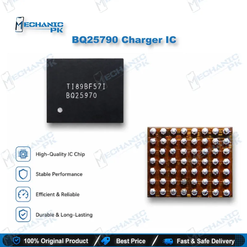
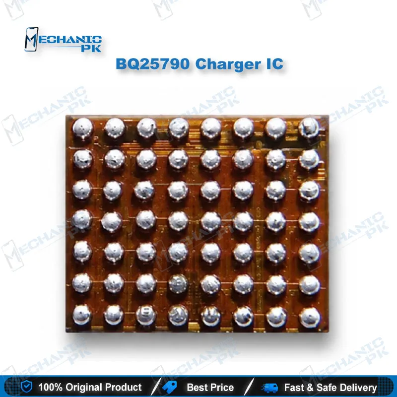
BQ25790 Charger IC – 1-4 Cell 5A Buck-Boost Battery Charger
₨ 550
5A Buck-Boost Charging for 1–4 Cell Packs
The BQ25790 Charger IC is a fully integrated switch-mode buck-boost charger for 1–4 cell Li-ion and Li-polymer battery packs, with charge current up to 5A. Its four integrated switching MOSFETs and battery FET remove the need for an external power stage, and the converter moves between buck, boost, and buck-boost modes automatically as input and battery voltage change. I2C control, dual-input power selection, and USB OTG discharge give engineers precise control over charging behavior. Low 600 nA shutdown current and input and battery overvoltage and overcurrent protection support a compact 56-pin WCSP design for portable power boards.
The BQ25790 Charger IC is a fully integrated switch-mode buck-boost charger built for 1–4 cell Li-ion and Li-polymer batteries, and it covers the core charging function of a BQ25790 buck-boost charger IC design on a modern charging board. The device integrates four switching MOSFETs, the battery FET (QBAT), input and charging current sensing, and all loop compensation for the converter, so the board does not need a separate external power stage for charging. Because the converter selects buck, boost, or buck-boost operation on its own based on input and battery voltage, one design can handle inputs that sit above or below the battery voltage without host intervention. Charging runs through trickle, pre-charge, constant current, and constant voltage phases. In the constant voltage phase, the IC terminates the cycle once the current drops below the programmed termination threshold, and it starts a new cycle when the battery falls below the recharge threshold. Engineers who need host control can configure charge parameters over I2C, while autonomous mode lets the IC charge without a host processor, which simplifies early bring-up and boards without a dedicated charging controller. Dual-input power selection lets the design choose between two input sources, and power path management keeps the system rail supplied when the battery is fully discharged or removed. With no input present, the device supports USB On-The-Go by discharging the battery to produce an adjustable VBUS between 2.8 V and 22 V in 10 mV steps, which suits reverse-charging accessory designs. Protection features include NTC battery temperature monitoring, trickle, pre-charge, and fast-charge timers, and input and battery overvoltage and overcurrent protection. Quiescent current stays low, with a typical 600 nA draw in charger shutdown mode, which matters for standby-sensitive portable hardware. The IC ships in a 56-pin, 2.9 mm × 3.3 mm WCSP package, so rework calls for a hot-air station with a precise nozzle, controlled preheat, and clean flux handling rather than a standard iron. On the bench, this charging architecture is where a technician should check first when a dead phone shows a detected charger but no charging, or when the device stays dead until the battery path is verified. Confirm the input path, the QBAT and battery-side connections, and the NTC wiring before replacing the IC. Use the I2C register configuration as a diagnostic reference when the charging profile looks wrong. Technicians and engineers who handle charging circuit repair, power path troubleshooting, or reverse-charging design will find the BQ25790 useful as a reference for how a modern 1–4 cell charger behaves across every operating mode, from shutdown through full charge.
| Weight | 0.1 kg |
|---|
Key Features
- Supports 1–4 cell Li-ion and Li-polymer batteries
- Charge current up to 5A
- Four integrated switching MOSFETs with automatic buck, boost, and buck-boost selection
- I2C controlled, with autonomous charging mode available
- Dual-input power selection
- USB OTG discharge with adjustable VBUS from 2.8 V to 22 V in 10 mV steps
- Typical 600 nA quiescent current in shutdown mode
- Input and battery overvoltage and overcurrent protection, with NTC battery temperature monitoring
Specifications
| Brand | Texas Instruments |
|---|---|
| Model | BQ25790 |
| Category | Battery Charger IC |
| Compatibility | 1–4 cell Li-ion and Li-polymer battery packs |
| Technology | Synchronous switch-mode buck-boost charger, I2C controlled |
| Output Voltage | Adjustable VBUS 2.8 V–22 V in 10 mV steps (USB OTG mode) |
| Dimensions | 2.9 mm × 3.3 mm (56-pin WCSP package) |
Common Repair Uses
- Replacing a faulty charging IC on boards with a 1–4 cell buck-boost charging stage
- Diagnosing no-charge faults by checking input detection, power path, and battery connections
- Troubleshooting dead phone cases where the battery path must be verified before IC replacement
- Checking NTC battery temperature wiring when charging stops or behaves unpredictably
- Analyzing USB OTG and reverse-charging behavior on accessory and power-bank boards
- Reballing and reworking the 56-pin WCSP package with a hot-air station
Compatible Devices
- 1–4 cell Li-ion battery packs
- 1–4 cell Li-polymer battery packs
- Dual-input charging designs using power source selection
- Reverse-charging and USB OTG designs requiring a 2.8 V–22 V VBUS output
FAQ
What is the product name?
What is the brand of this product?
What is this product used for?
Who should use this product?
Does this IC support USB OTG output?
Can this IC charge a 4-cell battery pack?
Related products